PeteJ wrote:
I have fitted the grips and run all the wires, but as pointed out , the bike side auxilliary conector is not there so I can not connect the male and female auxilliary power connector on the heated grip side . I see your circuit diagram but am not sure what in the diagram is original equipment and what is new and has to be purchased extra.
Any chance please you can put me in the right direction on how I can connect to the switched power supply please. I see that you say in the circuit diagram "Cut off the female AUX connector (and wuiire) from switcgear and connect to the relay"
Howeever I am not fully understanding what I need to cut, or do I need any new wiring etc
The two power connectors are visibe in the photo.

So, in the absence of another female power connector (to the left in your photo) my method is to trace this back as far as possible into the heated grip loom, whilst unwrapping the loom tape) and cut it off (with lots of wire to the connector). Cut the wires at different points so you can wrap them back up with the loom tape. You could always cover the ends with heatshrink too.
Then, with this connector and wire, put some spade terminals on and connect it up to the relay in the diagram.
Alternatively you can look for another connector, so as you don't need to modify your loom, but saying that, what else would you want to connect? The connector is a Sumitomo 2 pin, Buell part numbers Y0226.1AK (housing) Y0228.1AK (terminal)
Should you wish to connect something else into the loom, the male is Y0170.5A8, but the terminals are not listed in the parts book. You would have to find some that fitted, either by PMing
plumpton or looking
here...
PeteJ wrote:
This is what you posted- the diagram
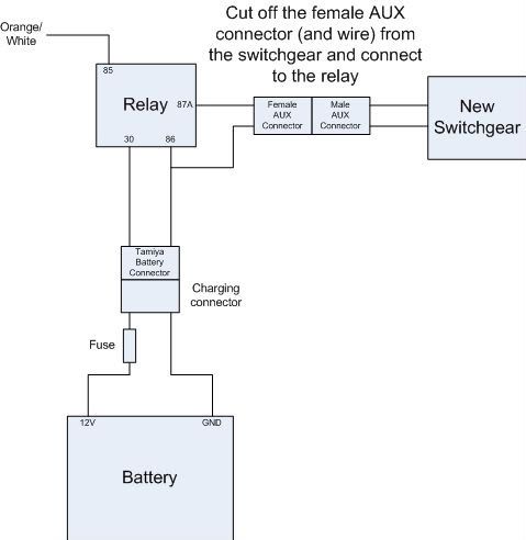
You don't need to use the charging connector, but it saves having to hack into your main loom for a 12V source.